DIY Cruise Control on Polo 9N3 WITH pictures
Posted: Wed Apr 17, 2013 12:56 pm
I could not find any detailed instructions on the internet to do this my self, so decided to make my own DIY!
Here goes....
First the fitting instructions from the internet ....badly translated from German by someone else.
The installation and in particular the expansion of the air bag must be performed by appropriately trained professionals! We accept no liability for damage caused by installation. This manual is an installation tool and has no claim to completeness.
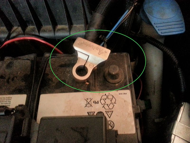
Please disconnect the battery before any maintenance work. The installation is at your own risk, the KUFATEC shall be liable for any damages.
Please route the wiring in an appropriate manner invisible from the seats to the following ports.
Required components:
1 VAG Com software, Laptop, Diagnostic Line
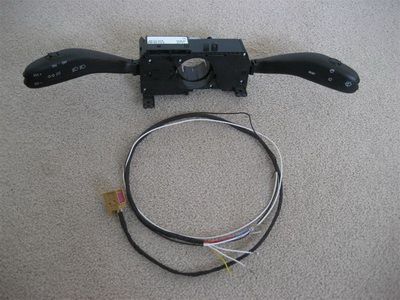
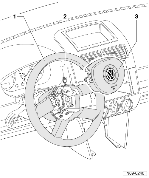
2 Steering column with GRA function
3 Line set of www.kufatec.de
First, the engine control unit for GRA is coded. This login via computer with the diagnostic code 11 463 and engine control unit.
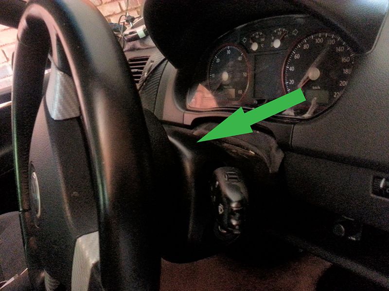
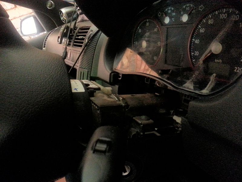
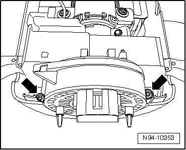
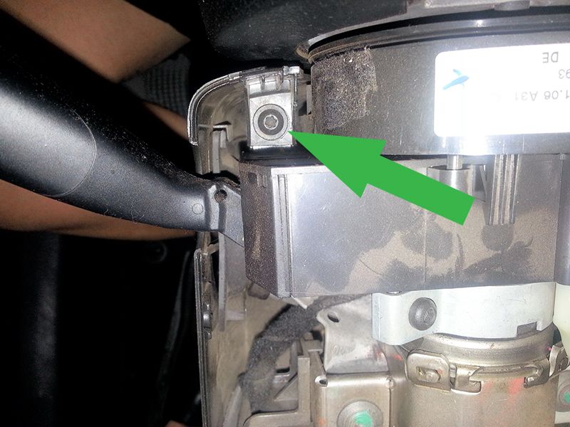
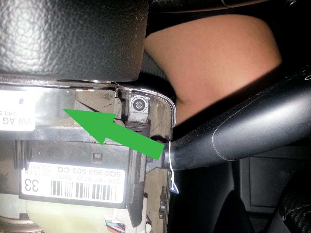
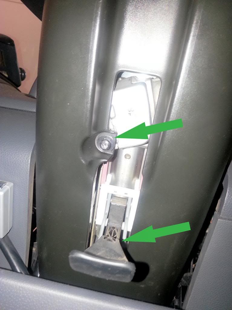
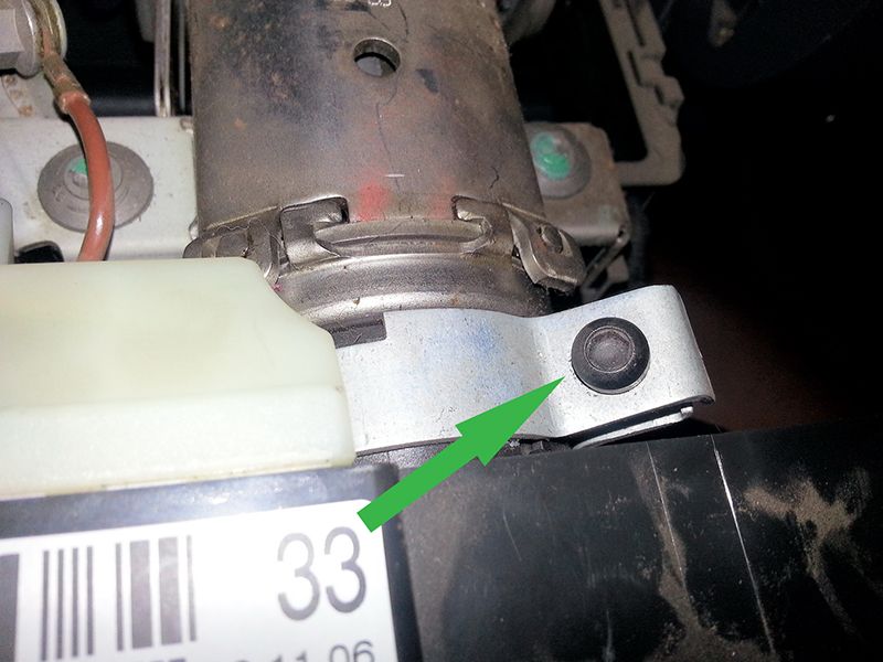
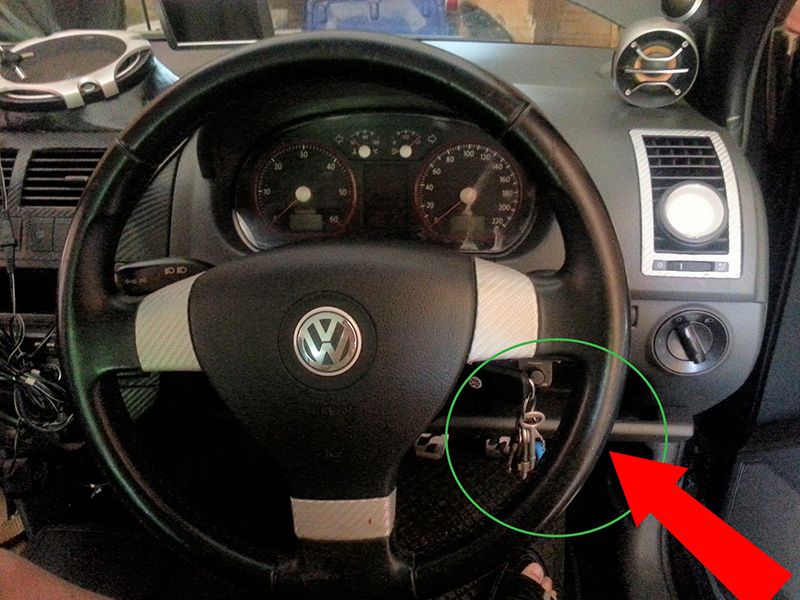
1. Small fairing next to the steering wheel (driver up with a screwdriver). The 2 torx screws from the diagnostic connector solve. Loosen the clamp from the front board controller and this bear down.
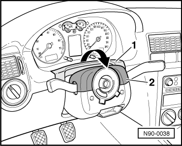
2. Trim around the steering wheel (only clipped)
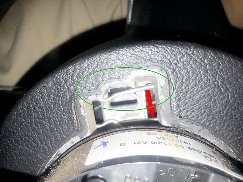
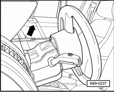
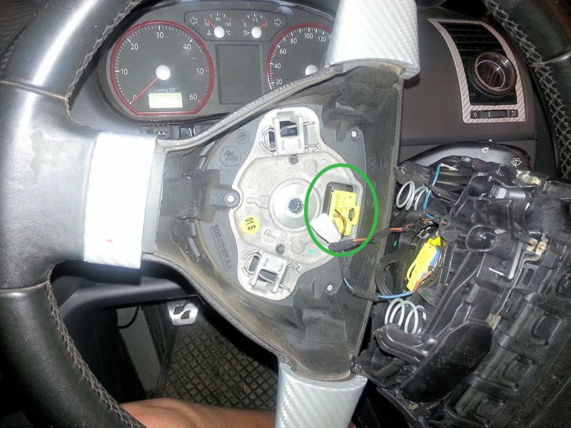
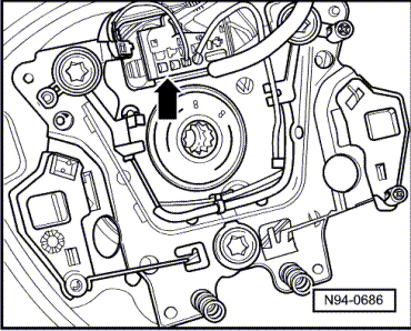
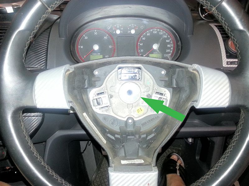
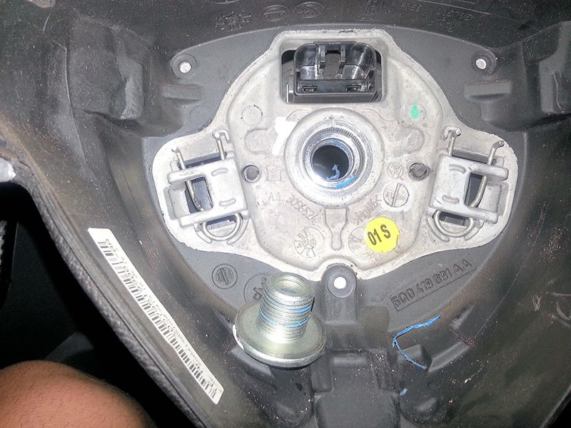
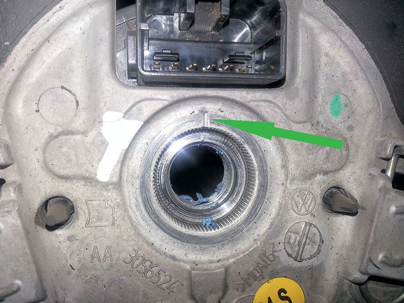
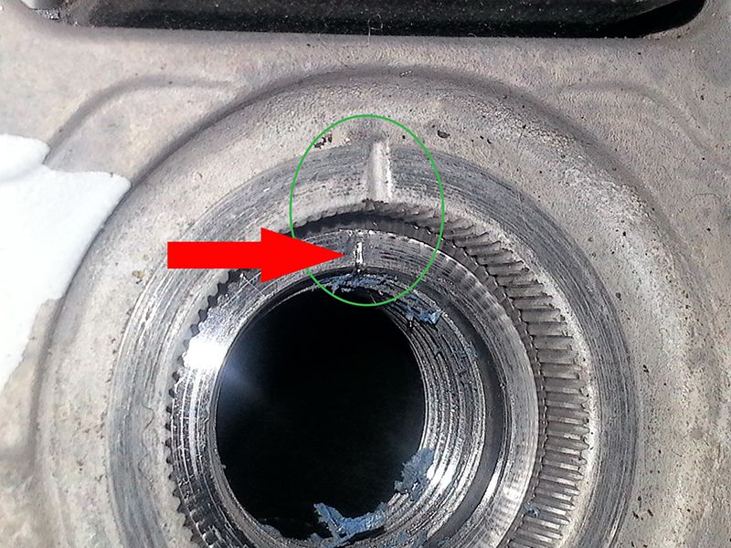
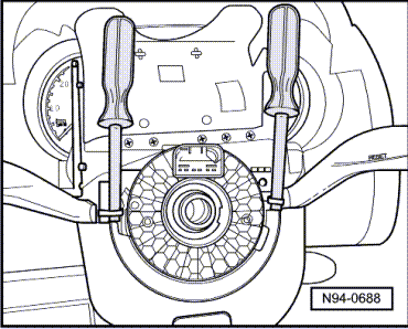
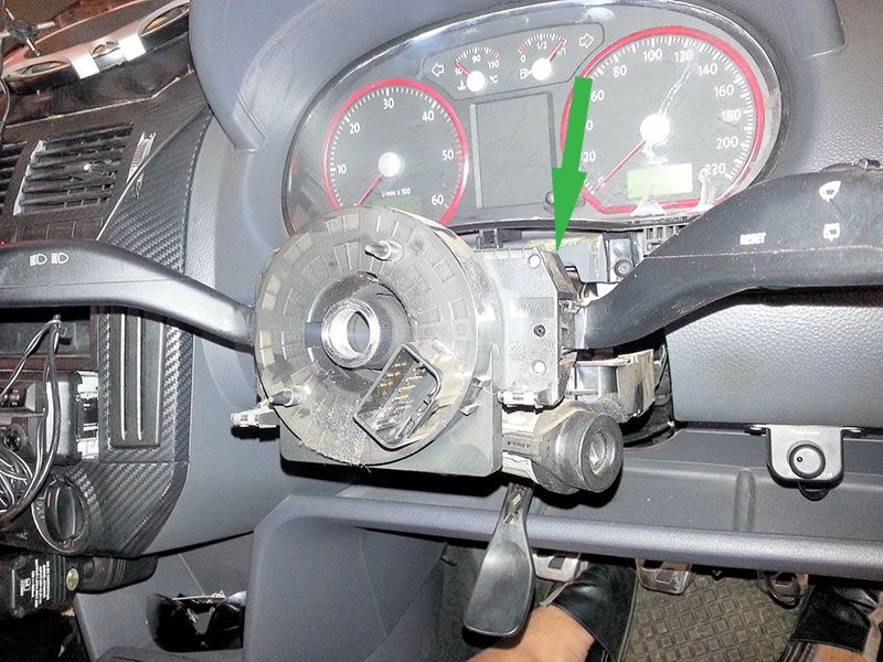
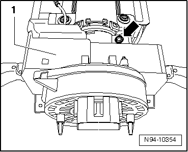
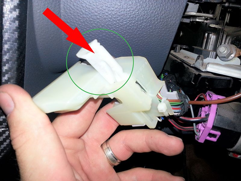
3. Remove steering wheel. The right and left are from the back 2 approx. 8mm wide holes in the steering wheel. The steering wheel rotated 90 degrees. Now a middle screwdriver side up in this hole. Screwdriver and lift the airbag unit should disengage. Airbag unit separate from all the plugs and remove. Now the steering wheel to make it absolutely straight and release the inner drive screw and pull off the steering wheel. The position of the movable ring below may be changed under any circumstances. Now the compact connector solve (pull out the white slide lock). The steering column is released to the metal ring and against the new function with GRA changed.
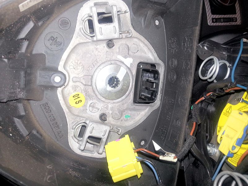
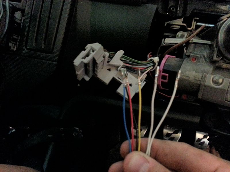
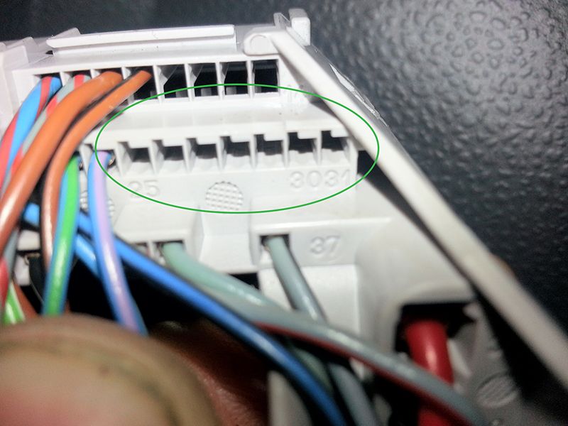
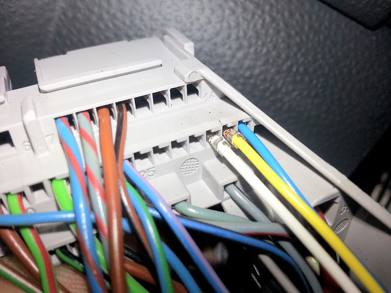
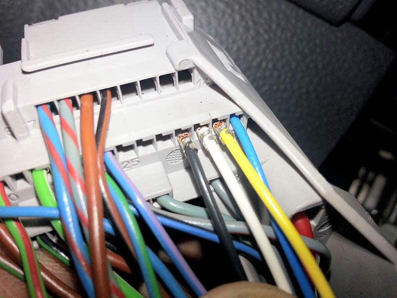
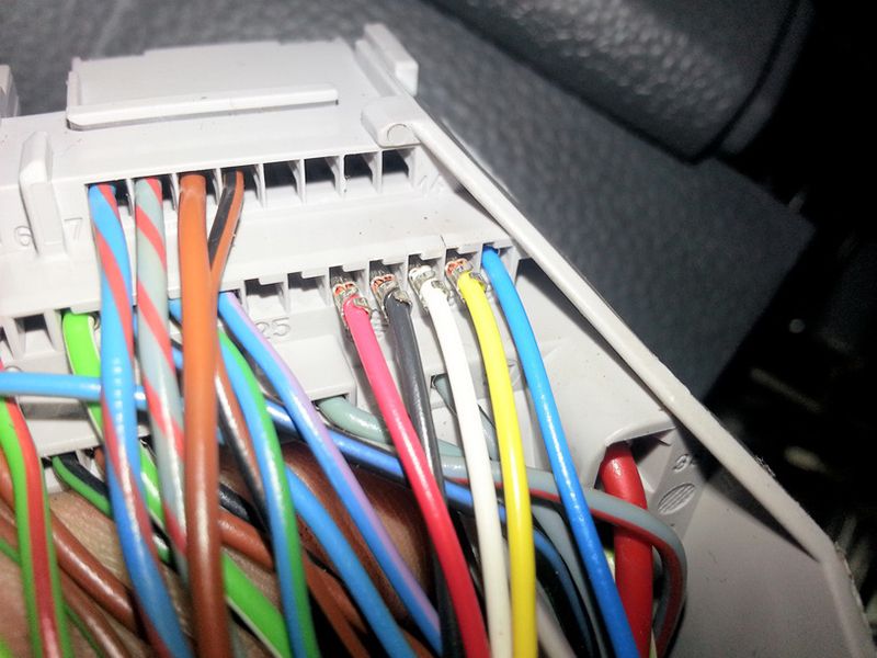
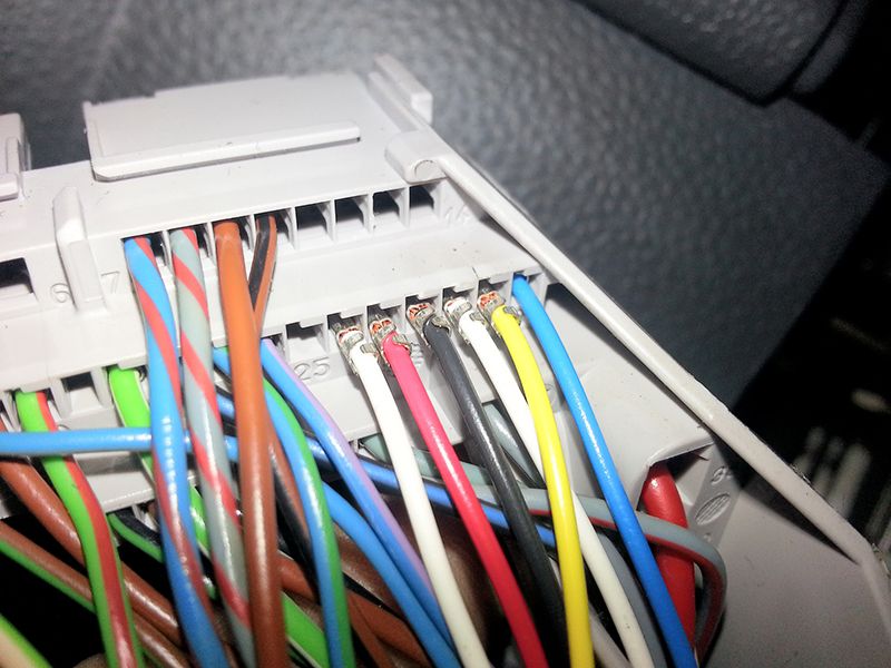
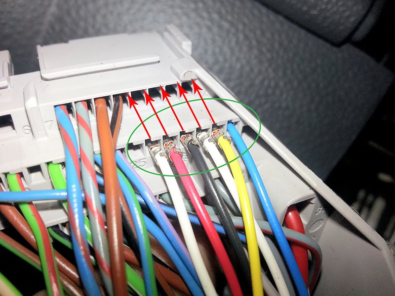
4. Now the cable set is used. First, remove the cap on the side. Then, the individual cables plug into the compact connector.
PIN 26 - white
PIN 27 - red
PIN 28 - black
PIN 29 - white
PIN 30 - yellow
PIN 31 - blue
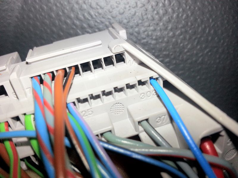
Then run the wiring along the cable channel on the steering column under the panel in the direction of the network control unit and at the same place the
black wire to the fuse box
and the white wire to the plug unit bulkhead.
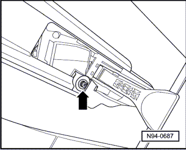
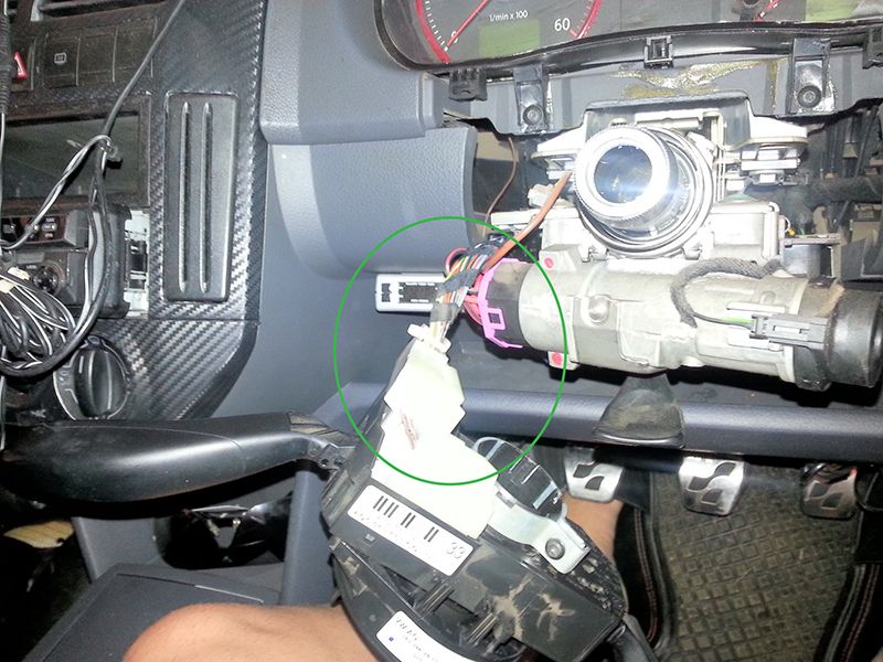
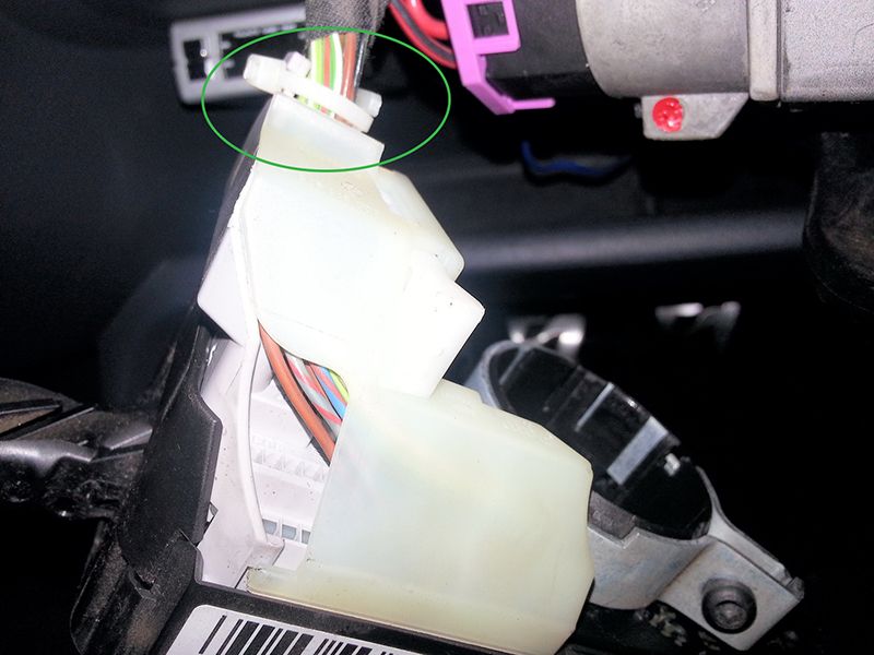
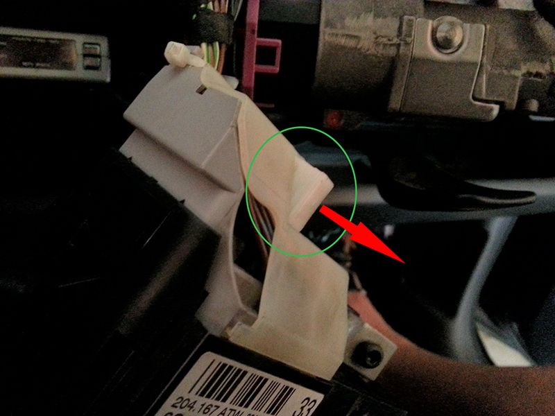
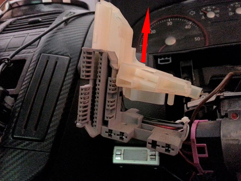
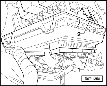
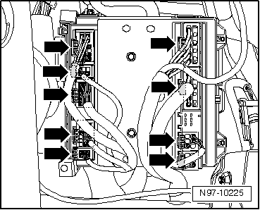
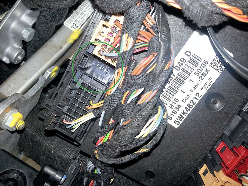
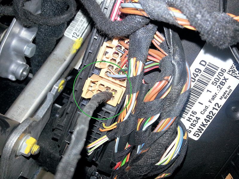
5. Connect the white wire to the white 11-pin connector on the firewall. With a suitable light source (torch) you can see the plug on the end wall to the engine room through the small hole next to the steering column. If necessary, remove the relay bracket by pulling it. This has left and right locking hook. Time to move with a long screwdriver, first the metal lock to the left. Now remove the white plug to the inside (above the OFF position). The pink additional locking arm and insert the white wire in pin 10. Interlock the plug, plug in and do not forget metal latch.
To PIN 10 (here the red line), the white wire going from the harness.
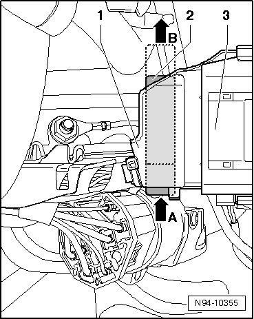
6. To connect the power supply (Kl.87) the black wire of the GRA is cable set to secure the fuse holder connected SB4. The fuse holder can, after having loosened the two screws, push down into the foot well. First, remove the cap. The fuse is SB4 already occupied. Connect the black wire to the existing black / blue wire, solder and wrap with electrical tape. The fuse size must not be changed.
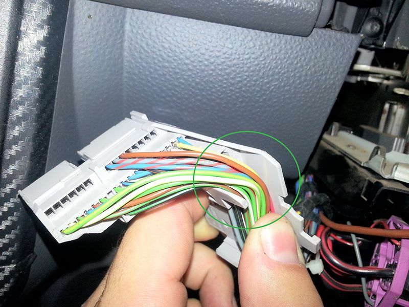
7. The brown connector coming from the bottom of the board XS3 controller with the name. The connector is coded it only fits into this one box.
8. Reassemble in reverse order. First screw the fuse holder, then secure the relay board and the network control unit, diagnostic connector screw cap and push the steering wheel.
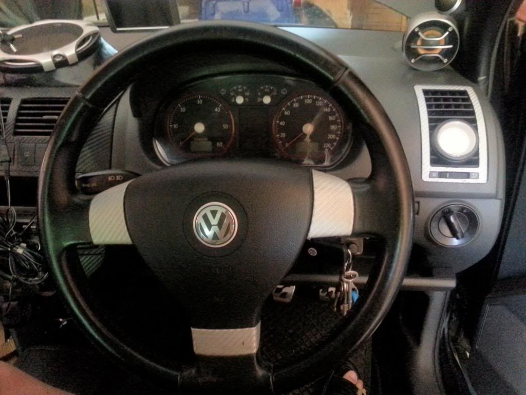
From model year 2003, the display for the GRA (green icon in the centre) is the instrument panel as standard.
To further clarify the connections, as the German instructions weren't that clear even if you spreken ze deutch, which I don't, they are as follows.
1. (white) ECU 46 cruise on/off
2. (Blue) ECU 45 Resume
3. (red) ECU 44 Set
4. (Black) ECU 14 Enable cruise (& connect to ignition 12V for stalk)
The colours of course are arbitrary, 1 to 4 is the connection to the proper stalk control if required.
Enable & on/off I connected to 12V permanently (ignition switched), set & resume push switches are momentary connections to 12V.
All the connections can be tested in VAG COM by reading measuring block 022 in the engine controller (ECU)
00000X Enable cruise
0000X0 Cruise on/off
000X00 Set
00X000 Resume
Once enable & on/off are connected to 12V, a read of block 006 RHS box value shows a 1.0 indicating cruise is active.
Here goes....
First the fitting instructions from the internet ....badly translated from German by someone else.
The installation and in particular the expansion of the air bag must be performed by appropriately trained professionals! We accept no liability for damage caused by installation. This manual is an installation tool and has no claim to completeness.
Please disconnect the battery before any maintenance work. The installation is at your own risk, the KUFATEC shall be liable for any damages.
Please route the wiring in an appropriate manner invisible from the seats to the following ports.
Required components:
1 VAG Com software, Laptop, Diagnostic Line
2 Steering column with GRA function
3 Line set of www.kufatec.de
First, the engine control unit for GRA is coded. This login via computer with the diagnostic code 11 463 and engine control unit.
1. Small fairing next to the steering wheel (driver up with a screwdriver). The 2 torx screws from the diagnostic connector solve. Loosen the clamp from the front board controller and this bear down.
2. Trim around the steering wheel (only clipped)
3. Remove steering wheel. The right and left are from the back 2 approx. 8mm wide holes in the steering wheel. The steering wheel rotated 90 degrees. Now a middle screwdriver side up in this hole. Screwdriver and lift the airbag unit should disengage. Airbag unit separate from all the plugs and remove. Now the steering wheel to make it absolutely straight and release the inner drive screw and pull off the steering wheel. The position of the movable ring below may be changed under any circumstances. Now the compact connector solve (pull out the white slide lock). The steering column is released to the metal ring and against the new function with GRA changed.
4. Now the cable set is used. First, remove the cap on the side. Then, the individual cables plug into the compact connector.
PIN 26 - white
PIN 27 - red
PIN 28 - black
PIN 29 - white
PIN 30 - yellow
PIN 31 - blue
Then run the wiring along the cable channel on the steering column under the panel in the direction of the network control unit and at the same place the
black wire to the fuse box
and the white wire to the plug unit bulkhead.
5. Connect the white wire to the white 11-pin connector on the firewall. With a suitable light source (torch) you can see the plug on the end wall to the engine room through the small hole next to the steering column. If necessary, remove the relay bracket by pulling it. This has left and right locking hook. Time to move with a long screwdriver, first the metal lock to the left. Now remove the white plug to the inside (above the OFF position). The pink additional locking arm and insert the white wire in pin 10. Interlock the plug, plug in and do not forget metal latch.
To PIN 10 (here the red line), the white wire going from the harness.
6. To connect the power supply (Kl.87) the black wire of the GRA is cable set to secure the fuse holder connected SB4. The fuse holder can, after having loosened the two screws, push down into the foot well. First, remove the cap. The fuse is SB4 already occupied. Connect the black wire to the existing black / blue wire, solder and wrap with electrical tape. The fuse size must not be changed.
7. The brown connector coming from the bottom of the board XS3 controller with the name. The connector is coded it only fits into this one box.
8. Reassemble in reverse order. First screw the fuse holder, then secure the relay board and the network control unit, diagnostic connector screw cap and push the steering wheel.
From model year 2003, the display for the GRA (green icon in the centre) is the instrument panel as standard.
To further clarify the connections, as the German instructions weren't that clear even if you spreken ze deutch, which I don't, they are as follows.
1. (white) ECU 46 cruise on/off
2. (Blue) ECU 45 Resume
3. (red) ECU 44 Set
4. (Black) ECU 14 Enable cruise (& connect to ignition 12V for stalk)
The colours of course are arbitrary, 1 to 4 is the connection to the proper stalk control if required.
Enable & on/off I connected to 12V permanently (ignition switched), set & resume push switches are momentary connections to 12V.
All the connections can be tested in VAG COM by reading measuring block 022 in the engine controller (ECU)
00000X Enable cruise
0000X0 Cruise on/off
000X00 Set
00X000 Resume
Once enable & on/off are connected to 12V, a read of block 006 RHS box value shows a 1.0 indicating cruise is active.